
I took the plunge into the 3D printing hobby a few years back. I’ve still got my first printer, a Bambu Lab A1, and I love it. Great machine. But I’m not a CAD person. I know enough Blender to get by, and I’ve built things I’ve printed there, but it’s not my favorite tool for making 3D printable objects. I’ve done some work in Fusion 360 and FreeCAD too. I enjoy Fusion more, but regardless, none of these are tools I’m deeply proficient in.
So it occurred to me to ask if an LLM could help with this too. I think I asked ChatGPT something like “what kinds of 3D model files can you generate?” and was actually kind of surprised by the answer. It listed out a bunch of different 3D formats it could produce. That kicked off a few months of experimenting.
As you probably already know, LLMs seem to do well with generating code, and OpenSCAD is essentially code. It’s a scripting language for 3D geometry. Variables, modules, boolean operations, all expressed in text. So the same way an LLM can write you a solid SVG or a well-structured HTML page, it can write OpenSCAD that produces real, printable geometry.
Of course there are diffusion-based approaches to 3D generation now, like how AI image generators work, but that’s not what’s happening here. This is actually constructing the object from code, the same way you’d build an app or a website.
STL files are essentially raw triangle meshes with no parameters or structure, just coordinates. LLMs seem to be able to produce those too, but the results were less precise and much harder to iterate on, at least for me so far. The OpenSCAD approach seemed to be more consistent overall.

Like most of these mental unlocks that come with Claude Code and similar tools, my brain was just going wild with ideas the moment it clicked.
But I’ve since learned that I have to keep myself grounded, because for every project where it helped me get from idea to printed object in an hour or an afternoon, there’s one where I spent way too much time going back and forth through 20-plus revisions before I realized I was spinning my wheels. I probably could have just modeled it myself in Blender or made myself learn Fusion better.
So I want to share where I’m at with it, what’s worked for me, and what hasn’t.
The Projects That Worked
Bulb Diffuser
This was my cleanest and fastest success. I had an LED bulb in a lamp and wanted a clip-on diffuser to spread the light more evenly into the lampshade. I was imagining a ring with grippy fingers that could clip onto the bulb, with a wide outer section thin enough to be translucent.
The bulb diffuser. A wide disc with clip fingers that grip the LED bulb.
Drag to rotate · Scroll to zoom · Right-click to pan
I built this one through my Claude Code + PAI setup. The AI wrote the OpenSCAD, and because it’s parametric by nature, all the key dimensions lived as variables in the file.
Working with OpenSCAD like this probably comes as no surprise to people who are already familiar with it, but this was my first time touching it. So that was a whole revelation on top of working with the AI tools to do it.
The AI handled the geometry well because it was relatively straightforward. The trickier part was figuring out the right thickness for light diffusion. My PLA became translucent at about 0.4mm, just two layers at standard layer height. That’s maybe a physics insight more than a geometry one. But once we had it, the parametric approach meant I could tweak the thickness and re-render quickly.
I only had to do about two print iterations, and that was mainly just dialing in the thickness. The final print clips onto the bulb and works exactly as intended.
Why it worked: Simple geometry that was easy to describe in words. Clear functional requirements (clip on, diffuse light). Easy to verify (does it fit? does light come through?). The code-based approach made iteration fast.
Film Developer Bottle Hooks
I develop color film at home and have a pretty basic DIY setup. I use an immersion circulator (the kind you’d normally use for sous vide cooking) to heat water in a dish tub. The developer bottles sit in the warm water to stay at temp, but they tend to drift around and could easily tip over.
I wanted a hook that clips over the tub edge and cradles a bottle to keep it in place. It wasn’t something I strictly needed to fix, but it was one of those things where if I could get a quick solution without spending a lot of time on it, that’d be great.
The bottle hook. Clips over the tub edge with a cradle for the bottle.
Drag to rotate · Scroll to zoom · Right-click to pan
This one I did through ChatGPT, before I had my current Claude Code setup. It generated the STL files directly through conversation. The process was iterative. First version, test fit, adjust dimensions, new version. I gave it the exact measurements (tub lip: 15.6mm, bottle diameter: 102mm) and described the mechanical concept I wanted. A clip with some pressing tension over the tub lip, and a half-cup cradle inside the tub for the bottle.
You can tell by looking at it that the result isn’t the prettiest piece of geometry. The shape is a little odd. But it only took one test print before we had something that worked, and I didn’t need it to look nice. I just needed something quick and functional. It’s the exact measurements of my bottles and the side of my inexpensive dish tub. A good scenario for this kind of AI-assisted design: getting from nothing to something useful quickly when precise fit matters more than aesthetics.
Why it worked: The shape was fairly easy to describe with measurements and mechanical behavior. Exact dimensions drove the design. The feedback loop was fast.
Film Scanner Leveling Plate
I wanted a way to level my film scanner easily without buying some fancy device from a photography store if I could help it. This ended up being a bigger project than the bottle hooks, with more iterations, but the exploration was worthwhile. It was fun, and it taught me a lot of terms and concepts about designing parts that I didn’t know before.
The base design was a flat rectangle with rounded corners, a hex grid pattern for rigidity without excess weight, and mounting bosses. But I wanted a little bit more.
I wanted embeddable screw holes for adjustable feet. A three-point leveling system, which the AI actually helped me figure out was more efficient than four-point for this application. And I needed it to mate correctly with my existing film scanner (a 3D printed scanner kit from Tone that I’d already assembled) and a specific LED light panel, holding both in place.
Main plate with hex grid and mounting bosses
Drag to rotate · Scroll to zoom · Right-click to pan
Adjustable leveling foot (screws into plate)
Drag to rotate · Scroll to zoom · Right-click to pan
This was another ChatGPT project, and it took a fair number of iterations to get the screw placement right, the fit with the existing scanner body, and the overall dimensions dialed in. The AI seemed to do well with this because the core geometry was still fundamentally flat 3D planes that we were just extruding. A flat plate with holes and bosses. And it helped me think through the leveling approach, which I wouldn’t have known to research on my own.
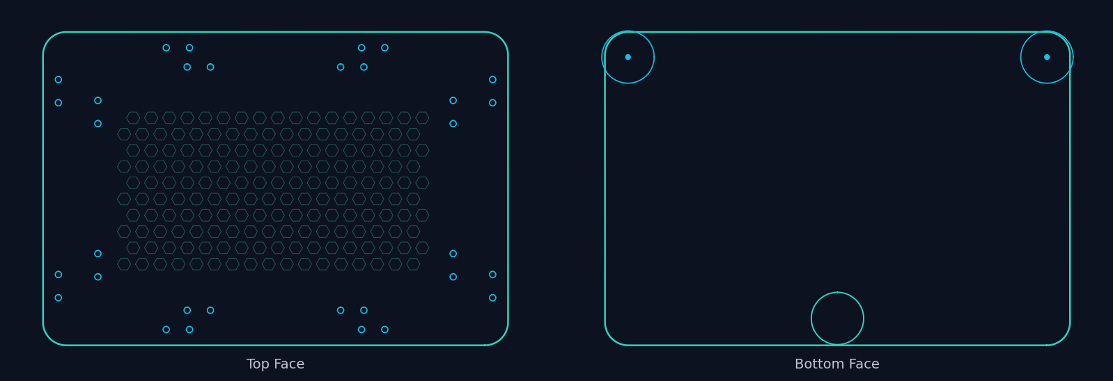
Why it worked: Essentially a 2D problem extruded into 3D. Precise measurements drove the design. The layout and the patterns were pretty straightforward.
Where It Struggled
Terraforming Mars Tile Grid
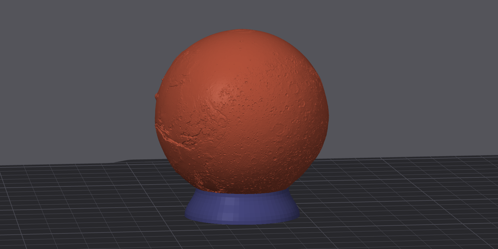
I play a lot of Terraforming Mars (tabletop game), and I’d had some initial luck getting AI to make me custom stuff for the game really quickly.
A little Mars globe on a pedestal to use as the first player marker. That came together fast and looked great.
So I got excited and decided to go a little bigger. I figured it would be pretty simple. I just wanted a frame to hold all 60 hex tiles on the game board. The board has a specific hex layout and I just had to tile it and get the dimensions right.
The full 60-hex grid layout. The grid geometry itself works well.
Drag to rotate · Scroll to zoom · Right-click to pan
That part did take some iteration, but I was enjoying the process. I got to bust out the calipers and check exact dimensions. We did a bunch of single-hex test prints to dial in the various insets and tolerances, and we arrived at one that worked really well. If you zoom in on the viewer above, you can probably see where the tiles sit.
But this hex grid is way too big to fit on my 3D printer in one piece. So we had to come up with a way to split it into four parts and join them back together. That’s where everything fell apart and I started wasting a lot of time and prints.
We tried dovetails. The shapes came out wrong. We tried magnet pockets. The geometry constraints (2mm base thickness, narrow solid ring between the tile pockets and the see-through openings) made it really difficult. The LLM would generate code that looked reasonable, but the physical results didn’t work, seemingly because it couldn’t “see” how the pieces actually fit together in 3D space.
Another problem seemed to be that I was asking it to make really tiny changes across a really small space, and I just didn’t have good words for what I actually needed. We weren’t connecting on the spatial relationships I was trying to describe. After 13 versions and multiple joining approaches, we have a grid that holds tiles perfectly but we’re still figuring out how the pieces connect.
I think I probably could have gotten there with more time. But the simplicity of the object also means I could probably just take what the AI has already built for me and do the simple joining modifications myself in Fusion or Blender. That’s actually probably what I’ll do next. It’s just taken a backburner because it turned out not to be a ten-minute LLM build.
Why it struggled: The joining problem required understanding how parts fit together in 3D space while dealing with tolerances, material constraints, and assembly angles all at once. I couldn’t explain the geometry well enough in words. Each joining method attempt required understanding clearances and physical constraints that text descriptions just don’t convey well.

The Pattern
Looking across all these projects, a pattern emerged:
AI seems to work well when:
- The geometry can be fully described with measurements and simple shapes
- The design is essentially “2D plus extrusion” or built from primitive solids
- The functional requirements are clear and testable (does it fit? does it clip?)
- You’re building something new from scratch rather than modifying existing geometry
- You can work through it in code (OpenSCAD) rather than raw mesh data
AI seems to struggle when:
- The design requires understanding how multiple parts physically interact
- Geometry is constrained in multiple dimensions simultaneously
- You can’t find the right words to describe what you need spatially
- You’re iterating on complex shapes rather than dimensions
The Workflow That Emerged
Here’s what I’ve settled on after a few months, and it’s the piece I’d actually recommend to other people.
Start with a 2D description. Before anything else, describe an overhead or side view. I’m not talking about actually drawing anything (I’m terrible at drawing). I mean describe it in the form of a 2D sketch and work with the AI on that. Get the dimensions and relationships nailed down in 2D before going to 3D. This forces you to think about how the parts relate to each other, and it gives the AI something concrete to work from.
Use OpenSCAD, not direct STL generation. This was the biggest lesson for me. Having the AI write OpenSCAD code instead of generating raw mesh data made a huge difference for me. The code is readable. It’s parametric. All the dimensions live as variables in the file. You can tweak and re-render without re-explaining the whole design.
Test prints along the way. This isn’t specific to AI-assisted design. It’s just good practice if you’re building anything for 3D printing. Print a small section first. A 4-hex test piece instead of the full 60-hex grid. A smaller version of the diffuser to test multiple thicknesses. This catches fit issues before you’ve spent hours printing the wrong thing.
Version your files, or ask it to version them for you. It helps to not overwrite your working designs. Let the AI know that you want to keep all of its versions so you can refer back to things. I was working in OpenSCAD source files for the most part, and then had it export STLs when I was ready to take something to the printer. But regardless of what format you’re working in, keep versions.
Have it build you something visual to iterate with. This was easier for me than a folder full of files or trying to talk about designs purely in text. I had the AI build me a viewer page early on where I could see renders from different angles, spin models around, and compare versions side by side.
The Skill and the Gallery
If you’ve seen some of my other projects, it should come as no surprise that I have it do this for me too. It’s a pattern I use a lot, and I love this part of the workflow.
Early on in the process, I asked the AI to build me a gallery-style view for each print project. Once I moved to the Claude Code + PAI workflow, I codified this into something more consistent. It’s a skill in PAI, basically a set of instructions that tells the AI how to generate these pages for each project.
For every version we work through, I get multi-angle renders (isometric, side, top views), an interactive STL viewer I can spin around in my browser or on my phone, and a version history showing how the design evolved. All of it served through my portal setup , so I can pull it up on any device without opening a modeling program or SSHing into anything.
I’m very visual, and generating web views of things has turned out to be one of the most useful patterns in this whole setup. I didn’t even know that Three.js could render STL files in a browser until I asked the AI about it and it helped me figure out how. The ability to see the model from multiple angles, compare it to the previous version, and then describe what to change next, all from a browser tab, makes the iteration loop feel really smooth.
The skill itself is what makes this consistent across projects. It’s a markdown file that gives the AI context about my printer specs, OpenSCAD patterns, design principles, and the gallery page structure. Any time I start a new print project, it already knows the workflow and where to put my renders and previews.
Is It Easier Than Learning CAD?
Sometimes. Probably not in general.
For the bulb diffuser and the bottle hooks, using the AI workflow was significantly faster for me than opening Fusion 360 would have been. That’s partly because I just haven’t spent the time with that program yet and may never get around to it. It’s not my world. The designs were simple enough that describing them in words was the fastest path from idea to object.
For the tile grid, I probably would have been better off doing the joining geometry myself in Fusion or Blender. The joining problem involved so many interacting physical constraints (clearances, material thickness, assembly angles) that going back and forth in text was just a clumsy way to approach it.
The sweet spot is functional parts with clear dimensions. Brackets, holders, clips, plates, enclosures. Things where I can say “I need a rectangle that’s 200mm by 135mm by 5mm with rounded corners and mounting holes here, here, and here” and get a working result. These are also the kinds of things that don’t need to look pretty, which helps.
If you already know CAD well, AI probably isn’t replacing your workflow. But if you’re like me and you’re competent enough but not fast in traditional tools, AI can get you from concept to printed object in an afternoon for the right kinds of projects. Just go in knowing it has limits, and be ready to iterate.
If You Want to Try This
The core of my approach is a set of instructions (a “skill” in Claude Code or PAI terms) that I give my AI assistant. It provides context about 3D printing: my printer specs, OpenSCAD patterns, design principles, and the lessons learned from projects like these.
Head on over to the repo for a draft of my 3D printing skill.
If you’re using PAI (here’s my setup ), the quick install is:
git clone https://github.com/chriscantey/skill-3d-printing.git
Then tell your assistant:
Read skill-3d-printing/INSTALL.md and follow its instructions.
It’ll walk you through setup, including asking about your printer specs. Manual install instructions are in the repo if you’d rather do it yourself.
I don’t think this skill is complete or even particularly well polished. It’s the result of a few months of trial and error, and it reflects what’s worked for me with the projects I’ve taken on so far. I would love it if someone who knows more about OpenSCAD, 3D modeling, or mechanical engineering could take this, improve on it, and share what they learn. It may be helpful to others who want to dive in and start playing around with this like I did, in a non-professional, just-for-fun sense.
Big picture, even without this skill, the workflow section above is the important part. Start with 2D descriptions. Use something like OpenSCAD. Print test pieces. Have it render you an interactive viewer or something to track your work. Keep your expectations calibrated. And remember that “just a language model” can mean a whole lot when the output format is code.